Fluid Mechanics and Hydraulic Machines Laboratory
Overview
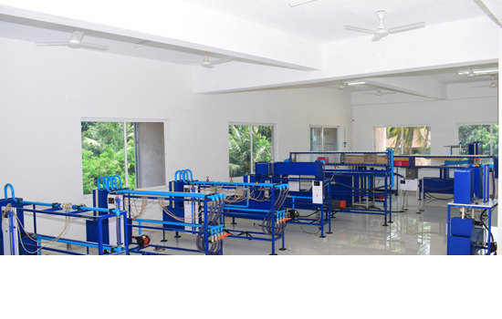
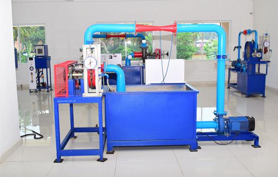
Fluid mechanics lab will enable the students to calibrate flow measuring devices, determine the force exerted by jet of water on vanes, measure discharge and head losses in pipes and understand the fluid pattern. It is a well-furnished laboratory with all the hydraulic machines like, turbines (Kaplan, Francis) Pelton wheel, Jet through vanes, weirs, notches, pumps from which students can understand the flow characteristics of a fluid and discharge properties. The total area of the lab is 230 sq. Meters.
Laboratory Area: 206.46 Sq. Mts
Laboratory Expenditure: Rs 18,67,200
Major Equipments
| Equipment Name | Specifications |
|---|---|
| Venturimeter | rcuric manometer with scale |
| Orificemeter | Area of measuring tank A = 0.2 x 0.4=0.08m2 Diameter of inlet pipe of Orificemeter d1 = 0.0254m Diameter of Orificemeter (throat)d2 = 0.0125m Differential U-tube mercuric manometer with scale |
| Major loss in Pipes setup | Electrical service:230 volts, AC 1 phase with earth connection. Make: Kirloskar. Measuring tank area :0.2x0.40 m2. Pipe length between two tapings :1.5 meter. Differential U-tube mercury manometer with scale. Mild steel pipes of 1â€, ¾†, ½†and also a 1†PVC pipe. |
| Notches | Angle of notch (for V notch) 90 Breadth of notch ( for rectangular notch and weirs ) L=75 mm Cross section area of collecting tank A= 0.12m2 Width of notch crest is 7cm |
| Weir | Area of the collecting tank A = 0.6 x 0.45 = 0.27m2, Width of Ogee weir b = 230mm, approach channel with baffle plates in it and fitted with ogee weir/broad crested weir, a surface level hook gauge to measure the head over notches, a constant steady supply of water with a means of varying the flow rate using Centrifugal pump. |
| Venturiflume | Breadth of inlet = B = 220 mm Breadth of throat= b =110 mm |
| Centrifugal Pump | Electrical supply: 220V, 1Phase, Motor: belt drive connected variable speed motor Single stage pump Delivery pressure gauges: 0-7 Kg/cm2 Vaccuum gauge: 0-760 mm of Hg Delivery control valve: For control flow rate of water(delivery valve) Suction control valve: For control flow rate of water(suction valve) Measuring Tank size: 400m x 400m |
| Vertical orifice | Diameter of the orifice d = 0.004m Area of collecting tank A = 0.2 x 0.3 = 0.06 m2 |
| Impact on Jet | A nozzle of 8mm diameter, a force indicator, Counter weights, a rotameter and different vanes like Flat, Inclined, Semicircular are used in the ensemble. |
| Kaplan turbine Setup | Pump capacity: 7.5 Hp, low head (Kirloskar make) Guide vanes: 4 nos. Venturimeter details : Inlet diameter =100 mm Throat diameter=50 mm Loading unit: Break drum type Break drum diameter: 320 mm Runner diameter: 160 mm |
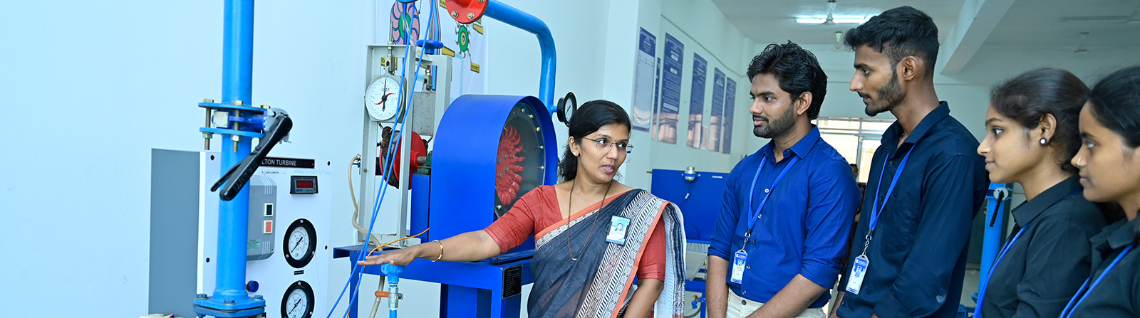
| Pelion wheel turbine setup | Pump capacity: 5 Hp, at 2700 rpm Make: Kirloskar Power: 3, 400v Venturimeter details : Inlet diameter =50 mm Throat diameter=25 mm Nozzle diameter=16 mm No of buckets: 20 no. Loading unit: Break drum type Break drum diameter: 220 mm |
| Flow visualisation setup | Diameter of the pipe = d = 28 mm = 0.028 m Area of the measuring tank = A = 0.03 × 0.03 = 0.009 m2 |
| Francis turbine setup | Pump capacity: 7 Hp, at 2700 rpm Make: Kirloskar Power: 3, 400v Guide vanes: 8 nos. Venturimeter details : Inlet diameter =100 mm Throat diameter=50 mm Loading unit: Break drum type Break drum diameter: 320 mm Runner diameter: 160 mm |
| Bernoulis theorem verification setup | Horizontal converging-diverging duct, Sump tank, Supply tank, Length of the collecting tank L = 0.3m and Width B = 0.15m , Power 380 W, Voltage 230 V, Manually operated |
| Reynolds Experiment | Diameter of the pipe (d) = 28 mm, Manually operated, Area of the measuring tank (A) = 0.03 × 0.03 |
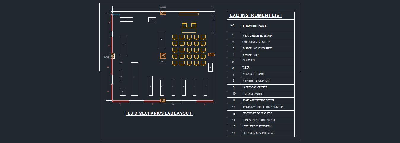
Laboratory Layout
Photos